Where Motor Energy Losses Occur
By John Malinowski | December 4, 2013
Category:When manufacturing plant owners and facility managers look for ways to reduce energy consumption, they often see lighting as the main opportunity, so it’s the first upgrade they make. In actuality, the percentage of total energy used in a plant for lighting is much smaller than the percentage used to power equipment and machinery.
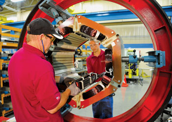
Nearly every component of a motor presents an opportunity for energy savings. Here, technicians insert stator coils into a large motor.
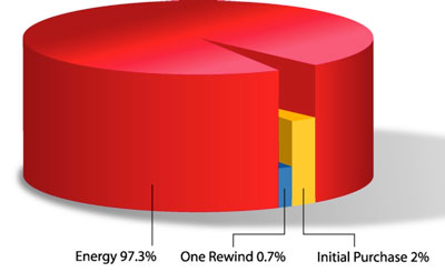
In industrial settings, motor-driven systems use 60 to 90 percent of the total power. The purchase price of an electric motor is only about 2 percent of the life cost (see Figure 1). Nearly 98 percent of life cost comes from the cost of the electricity the motor uses. To put that in perspective, the purchase price of an electric motor is equal to the cost of electricity to operate that motor continuously for about one month.
Where Losses Occur
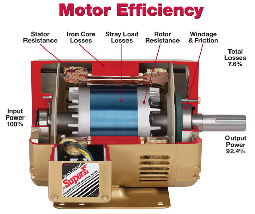
Energy efficiency is based on the losses inside the motor during power conversion from electrical to mechanical energy (see Figure 2). The major loss is stator resistance loss (stator I2R), which is the product of the square of the current multiplied by the resistance of the stator winding. The rotor also experiences I2R losses in the squirrel-cage rotor bars, called rotor resistance loss (rotor I2R). Core losses also occur, originating in the lamination steel. Core losses include hysteresis losses, which result from reorientation of the magnetic field within the motor’s lamination steel, and eddy current losses resulting from electrical currents produced between laminations due to the presence of a changing magnetic field.
These electrical currents occur in both stator and rotor cores, but primarily in the stator, as these losses are proportional to the frequency of the current. The frequency of current in the rotor bars is only a small fraction of the line frequency, as the rotor current frequency is proportional to slip (the difference between operating speed and synchronous speed). Both the stator and rotor laminations have an insulated coating to reduce shorting losses (eddy current) from adjacent laminations.
Friction losses are from the motor bearings and lubrication. Windage losses combine losses from the rotor spinning in air that creates drag and those from cooling fans used on the motor, along with friction losses in the bearings.
Stray load losses also are present. While these losses are not easily calculated, IEEE 112 method B provides a procedure for determining them based on test data. Typical loss breakdown for a 15-HP induction machine is shown in Figure 3.
| Stator resistance loss % | Rotor resistance loss % | Core loss % | Friction & Windage loss % | Stray load loss % | Total losses % | |
|---|---|---|---|---|---|---|
| Percent of losses | 30 | 20 | 19 | 13 | 18 | 100 |
| Percent of input | 3.8 | 2.5 | 2.4 | 1.6 | 2.3 | 12.6 |
Figure 3 Losses — such as these for a 15-HP induction motor — are not easily calculated, but they can be determined based on test data.
What Makes an Energy-efficient Motor Efficient?
While a more energy-efficient motor could be designed to reduce all of these losses, doing so might not be practical or cost-effective. Reducing the stator resistance by using more copper in the stator slot will decrease losses, but the slot fills in today’s motors already have reached the limit of practical manufacturability; there isn’t much room for improvement. Higher-grade lamination steel, or thinner laminations, can be used to reduce core losses. The higher-grade steel often is supplied in thinner laminations to reduce hysteresis and eddy current losses.
Increased stack length (the length of stator and rotor steel) can help reduce flux density and lower losses. Switching from an energy-efficient motor to one labeled by NEMA as a Premium® efficiency motor typically adds about 20 percent more stack length. With the thinner laminations, this adds about 40 percent more laminations, which again affects manufacturability and cost.
Rotor resistance and losses can be reduced, but not without affecting the motor’s performance. Inrush current may increase while the starting torque may decrease, and that’s not desirable. Some engineers add oversized bearings on each end of the motor, but that actually increases losses and lowers efficiency. On the plus side, loss reduction in the stator and rotor leads to fewer losses that need to be dissipated from the motor, so a smaller fan may be used, resulting in reduced windage losses.
As motor manufacturers consider the redesign of motors to raise efficiency, their engineers must balance the trade-offs in performance. Redesign can lead to higher inrush current, reduced starting torque, and less slip. If new laminations are used, the trade-off is that the winding equipment must be redesigned. These types of engineering redesigns can cost many millions of dollars per frame size — costs that usually are passed along to customers.
What’s Next Then?
The U.S. Department of Energy (DOE) currently is conducting a technical study to see if raising the efficiency level of motors above the NEMA Premium level is feasible and justifiable. The DOE continues to work with industry on this study and will announce its proposal in late 2013.
Motor manufacturers are reaching the limitations of physics on increasing the efficiency levels of conventional AC squirrel-cage induction motors. For some ratings, there is room to improve efficiency by about 0.5 percent. Some have proposed the use of die-cast copper rotors to reduce rotor losses and raise efficiency, but copper is a much more expensive material than the aluminum commonly used today, and new lamination designs will be required. Some DOE-sponsored tests have shown that die-cast copper rotors do not produce the gains that would appear feasible on paper. This is because the high heat from casting damages the insulating coating on the rotor laminations, causing additional losses and counteracting some of the anticipated gain. Copper rotors could be produced in high volumes with a fabricated cage using a robot for assembly, but this may be economically feasible only on motors 250 HP and larger.
Permanent magnet (PM) motor designs can yield high energy efficiency, but the rare-earth magnets used in these designs are costly. Research is being conducted on other magnetic materials, but few have the flux levels and temperature resistance-to-demagnetization required. New domestic sources of rare-earth material are expected, and perhaps these will add price pressure to the current Chinese suppliers. However, most of these PM designs require an adjustable-speed drive for operation, as few PM motors are available with line start capability at this time.
Other technologies, such as switched reluctance and synchronous reluctance motors, are being developed, but both require a drive for operation with no across-the-line operation. Currently OEMs seem to be gearing both to specific applications.
Best Approach for Maximum Energy Savings
Replacing inefficient motors with NEMA Premium efficiency designs is a first step toward energy savings, but additional savings can be realized by going beyond replacing one component in an existing system. Every component in the entire system should be analyzed, including the power distribution transformer, smart starter, soft starter, adjustable-speed drive, motor, mechanical power transmission components, and driven load. A system in which a 96 percent-efficient motor is powering a 50 percent-efficient load is not a good design.
System analysis should begin with selection of the most efficient pump, fan, or compressor, using best practices. That higher-efficiency machine will require less horsepower for operation, thus saving energy. Switching from a worm gear speed reducer to a helical or bevel gear system could improve that component’s efficiency from 50 or 60 percent to 95 percent. This also would allow use of a smaller motor, saving considerably more energy than the increase from an energy-efficient to a NEMA Premium efficiency motor design would provide.
Early in 2013 the DOE started a study to set efficiency levels for pumps, fans, and air compressors. This study will continue for the next several years and likely result in efficiency standards for these components by 2020.
Recent surveys seem to indicate the number of installed Premium efficiency motors is in the minority. Less efficient motors are being replaced on failure.
The History of Energy-efficient Motors
Obviously it’s important to have energy-efficient motors. But what exactly is an energy-efficient motor, and what makes it more efficient? A review of the history of these motors can help answer these questions.
Today’s high motor efficiency levels have been developed over the last 30 years. Several manufacturers introduced premium-efficiency motors in the early 1980s that comprised better lamination material, more active material (laminations and copper), and lower-loss cooling fans than their standard motors. However, there were no guidelines as to what efficiency level constituted a high-efficiency motor.
The National Electrical Manufacturers Association (NEMA) first made a distinction between standard and energy-efficient motors in MG 1-1987 with the September 1990 revision to its motor standard. These energy-efficient motor efficiencies later became the standards for the Energy Policy Act of 1992 (EPAct).
In October 1997 EPAct took effect, mandating minimum efficiency levels for general-purpose totally enclosed, fan-cooled (TEFC) and open drip-proof (ODP),1- to 200-HP (0.75- to 150-kW); 2-, 4-, 6-, and 8-pole; foot-mount motors. This act required that any EPAct motor sold in the U.S. comply with minimum nominal efficiency, testing, and labeling standards. EPAct did not cover special-purpose motors such as footless motors with C-faces, pump mountings, or other nonstandard configurations.
In 1996 the Consortium for Energy Efficiency (CEE) established premium-efficiency guidelines used by many utilities for rebate programs. By mid-2001, NEMA and CEE harmonized their efficiency standards, establishing NEMA Premium® efficiency standards for ODP and TEFC 1- to 200-HP (0.75- to 370-kW); 2-, 4-, and 6-pole motors in low and medium voltage. The NEMA-Premium standard first defined in NEMA MG 1-1998, Rev 2 does not differentiate between mounting configurations and all types of motors are covered.
The Energy Independence and Security Act of 2007 (EISA) next raised the efficiency levels of EPAct motors from energy-efficient designs as shown in Table 12-11 of NEMA MG 1 to those of Table 12-12 for Premium efficiency motors shipped after December, 2010. EISA also covered additional 1- to 200-HP nonstandard motors and 201- to 500-HP motors at the Table 12-11 energy-efficiency levels.
Additional efficiency levels for minimum-energy performance standards (MEPS) have been adopted in Canada and Mexico that basically follow the guidelines established in the U.S. Other countries have established MEPS as well. As of June 2011, the European Union set its MEPS at the equivalent of the U.S. EPAct level, with the level increasing to Premium level for 10- to 500-HP motors in 2015 and 1- to 500-HP motors in 2017.
Side by side, we move metal fabrication forward.
FMA unites thousands of metal fabrication and manufacturing professionals around a common purpose: to shape the future of our industry, and in turn shape the world.
Learn More About FMA


